
 +86 18068001229


0102030405
Review on Topology and Control Applications of Medium-High Voltage Power Electronic Transformers III
2025-09-18
3.3 Clamped Multilevel Topology
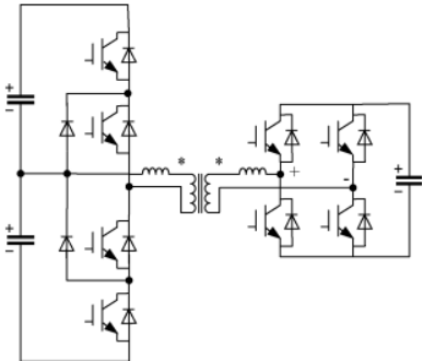
The Neutral Point Clamped (NPC) multilevel topology is shown. Besides the diode-clamped NPC topology , NPC topologies also include flying capacitor type and hybrid clamped type, among others. However, due to the large capacitor volume, NPC topologies still mostly use passive or active switching devices for clamping. Taking the diode-clamped multilevel topology as an example, in a three-phase rectifier stage topology, each phase leg consists of cascaded switching transistors and clamping diodes, connected in parallel to a single high-voltage DC bus. Literature proposed a single-phase PET topology with a rectifier stage using a four-level diode-clamped circuit. A single high-voltage DC bus is followed by input-series-output-parallel DABs, as shown . This topology can be expanded into a three-phase structure, and the number of voltage levels can be changed based on device withstand voltage levels and the high-voltage side voltage level. Like the MMC topology, the NPC topology can also be applied in the isolation stage, connecting the high-voltage DC bus to the Isolation Transformer, as shown. Literature applied a three-level diode-clamped NPC converter to the high-voltage side of an LLC resonant converter, verifying it on a 166kW/2kV~400V prototype. Literature applied a three-level diode-clamped NPC circuit to a three-phase DAB, achieving ideal DAB voltage and current characteristics.
When the NPC topology is used as the rectifier stage, it does not require isolated DC buses, reducing the number of isolation stage transformers. Furthermore, in three-phase structures, there is no double-line-frequency voltage ripple on the bus. However, because the clamped topology requires a large number of clamping devices, the number of clamping devices increases as the number of levels increases, making level expansion difficult and redundancy hard to achieve. In terms of control, the currents flowing into each bus capacitor of the NPC converter are different, leading to capacitor voltage imbalance. For NPC topologies above three levels, there is no effective voltage balancing algorithm. Additionally, inconsistent operating times of switches within and outside the arms lead to uneven heating, which can only be solved by changing the overall circuit topology .
The numerous difficulties caused by level expansion mean that NPC topologies can only be applied in medium/high voltage levels through device series connection or the use of high-voltage SiC devices. However, at lower voltage levels, compared to a single H-bridge topology, a three-level NPC has only half the voltage withstand and voltage stress on each switching transistor, while outputting more voltage levels, resulting in lower output filtering requirements. It has considerable application advantages as the inverter stage on the low-voltage side of a PET. For example, literature used a three-level diode-clamped NPC as the inverter stage of a PET to drive a three-phase motor, conducting experimental verification and achieving good motor drive performance and noise performance.