 +86 18068001229


0102030405
Review on Topology and Control Applications of Medium-High Voltage Power Electronic Transformers II
2025-09-18
2 PET Overall Structure Selection
PET topologies vary widely. Based on the number of energy conversion stages, they can be classified into single-stage, two-stage, and three-stage types [7]. Two-stage structures include those with high-voltage and low-voltage DC buses, as shown in Figure 1.
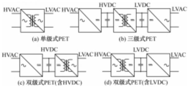
In single-stage PETs (Fig. 1(a)), a medium/high-frequency Isolation Transformer connects AC/AC converters on both sides. The primary-side AC/AC converter modulates the input line-frequency AC voltage into high-frequency AC voltage, which is coupled through the transformer and then converted back to line-frequency AC voltage by the secondary-side AC/AC converter. Single-stage PETs have fewer conversion stages and fewer components, high efficiency, and high power density. However, the lack of a DC bus makes them unsuitable for hybrid AC/DC grids, and power decoupling control is complex.
Two-stage PETs feature a DC bus on either the high- or low-voltage side. The topology on one side of the isolation transformer resembles that of a single-stage PET, while the other side connects to the DC bus via AC/DC or DC/AC circuits (Fig. 1(c) and Fig. 1(d)). With high- or low-voltage DC links, two-stage PETs can connect to medium/high-voltage DC grids on the high-voltage side or to PV/storage systems on the low-voltage side. However, the active power transferred by converters on both sides of the isolation transformer is highly sensitive to transformer leakage inductance parameters. Additionally, the DC bus capacitor experiences significant double-line-frequency voltage fluctuations, and converter current fluctuations are large [7], making control challenging.
Three-stage PETs (Fig. 1(b)) have DC buses on both high- and low-voltage sides. Input line-frequency AC current is rectified to a high-voltage DC bus via AC/DC conversion, modulated into high-frequency square waves, coupled to the low-voltage side via a medium/high-frequency transformer, rectified to a low-voltage DC bus, and finally inverted to line-frequency AC voltage via DC/AC conversion. Three-stage PETs can connect to both high- and low-voltage DC systems. Control of each conversion stage is relatively independent, facilitating decoupling and compensation control. However, multiple conversion stages result in the most complex structure. Due to the multi-stage design, three-stage PET topologies more easily achieve cascading on the high-voltage side and paralleling on the low-voltage side, meeting medium/high voltage application needs. Thus, three-stage topologies are the most widely used in medium/high voltage PET research and applications.
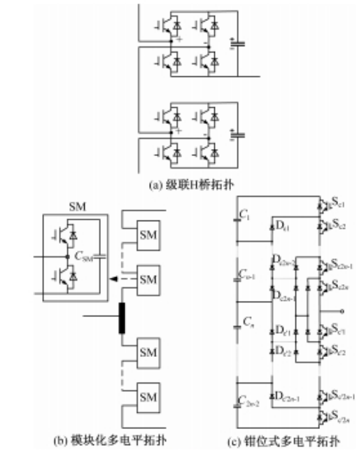
For PETs in medium/high voltage applications, the low-voltage side has low voltage levels with minimal device voltage constraints. In contrast, the high-voltage rectification stage and intermediate isolation stage face high voltage levels, imposing stricter requirements on circuit topologies and devices. Existing research focuses on two directions: ① New topologies and control methods for medium/high voltage PETs based on existing device voltage ratings; ② PET topologies and controls using new high-voltage devices, such as 10kV SiC devices [8, 9]. However, high-voltage SiC devices are still in the laboratory R&D phase, and commercial devices cannot yet meet voltage requirements. Therefore, multi-module cascaded or single-module multilevel topologies are used to meet high input voltage requirements. Typical topologies are shown in Figure 2, analyzed in Section 3.