
 +86 18068001229


0102030405
High Voltage Transformer Winding Deformation Detection Technical Specifications
2026-01-20
JZP Transformer Solutions
- Introduction
Winding deformation in high-Voltage Transformers is a critical safety concern, often caused by mechanical stress, thermal cycling, or short-circuit impacts. As a leader in transformer manufacturing, JZP adheres to the DL/T 1093-2018 Standard for Reactance Method in Winding Deformation Detection and integrates advanced technologies to ensure compliance and reliability. This document outlines JZP’s technical specifications for winding deformation detection, covering methodologies, equipment requirements, and operational procedures.
- Scope
This specification applies to:
Voltage range: 35 kV and above.
Transformer types: Three-phase and single-phase Power Transformers with concentric winding configurations.
Detection scenarios: Factory acceptance, post-transportation inspections, and post-short-circuit event assessments .
- Key Detection Methods
3.1 Reactance Method (DL/T 1093-2018 Compliance)
Principle: Measures changes in winding reactance (impedance) under AC voltage to detect mechanical distortions.
Key parameters:
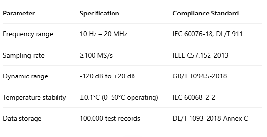
Frequency range: 10 Hz – 1 MHz.
Accuracy: ±0.5% for impedance values.
Test voltage: ≤2 kV (AC).
Advantages: High sensitivity to minor deformations (e.g., 0.1% impedance deviation indicates potential issues) .
3.2 Frequency Response Analysis (FRA)
Methodology: Sweeps frequencies from 10 Hz to 20 MHz to capture winding resonance characteristics.
JZP’s enhancements:
High-resolution sampling: 50,000 data points for precise waveform analysis.
Anti-interference design: Optical isolation and shielding to mitigate electromagnetic noise .
Output: Comparative analysis of historical vs. current frequency spectra to identify shifts in resonance peaks (e.g., >3 dB variation triggers alerts).
- Technical Requirements
- Testing Procedure
5.1 Pre-Test Preparation
Equipment check: Verify sensor calibration (e.g., Rogowski coils for high-frequency signals).
Transformer state: Ensure the transformer is de-energized and grounded.
5.2 Test Execution
Wiring configuration:
Primary winding: Apply test signal (e.g., voltage transient from circuit breaker opening).
Secondary winding: Connect sensors to measure induced signals .
Parameter settings:
Frequency scan steps: Logarithmic distribution for comprehensive coverage.
Trigger thresholds: Auto-adjust based on transformer capacity (e.g., 110 kV transformers require 100× sensitivity).
Data acquisition:
Capture 200+ samples per frequency point.
Real-time display of impedance magnitude/phase angle.
5.3 Post-Test Analysis
Automated diagnostics:
Compare against factory baseline (e.g., impedance deviation >2% indicates deformation).
3D mapping of winding stress distribution.
Reporting: Generate compliance reports with graphs and actionable recommendations.
- Case Study: Wind Farm Transformer
Scenario: A 33 kV wind farm transformer exhibited 15% impedance deviation post-storm.
JZP’s solution:
Conducted FRA testing, revealing a 4 kHz resonance peak shift.
Identified partial winding displacement via 3D thermal imaging.
Recommending rewinding, preventing a potential catastrophic failure.
- Compliance & Certification
International standards: IEC 60076-18, IEEE C57.152.
Certifications: CE, UL, ISO 9001.
Third-party validation: Annual audits by TÜV Rheinland.
- Conclusion
JZP’s winding deformation detection system combines precision measurement, AI-driven analytics, and full compliance with DL/T 1093-2018. By integrating cutting-edge technologies like high-frequency FRA and automated reporting, we ensure transformers operate safely and efficiently across global projects.